|
|
|
http://e.domaindlx.com/xcnick/NP/pics/04_04_13_wave.jpg
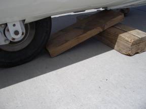
Figure 1 Ramp (2 boards) to put glider on saw horses in position
One can lift the fuselage on the saw horses, but one can’t lift the glider off the saw horses when the glider is assembled. So hence the ramp.
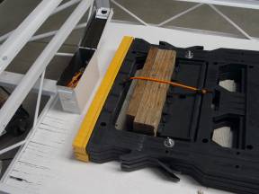
Figure 2 Ramp on trailer bungeed in saw horses
I have tried to put everything on the trailer so things won’t get left behind by the retrieval crew.
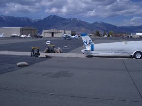
Figure 3 Saw Horses ready before unloading trailer
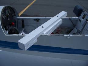
Figure 4 Special 2 by 4s lay crooked and then straighten to lock in place
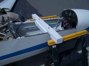
Figure 5 Special 2 by 4 on Saw Horse and Ramp under wheel
In position the saw horses are very close to the fuselage and can scratch if too much jerking around is used to assemble the wings. The saw horses can slip out from under the board allowing the fuselage to fall down. Do take off the horizontal stabilizer just in case this happens. I will be adding a lip to the special 2 by 4s so the saw horses can’t slip out so easily.
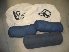
Figure 6 The arm pillows to lay the root of the wing on the ground.
One would rather put the fuselage on the trailer first, so one must lay the wings on the ground. The tip is supported by the wing tip wheel, but the root section could use some protection. Use these armrest cushions to protect the root section from being scratched on the ground.
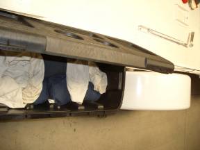
Figure 7 Pillows in the side box of the trailer
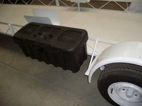
Figure 8 This Contigo SUV box mounted to side rail
There is not much support with it just bolted to the side rails, so only put the light weight stuff like:
(see pillow picture above) Most important, don’t forget to check that the canopy cover!
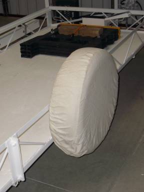
Before driving, make sure this cover is secured in the back with a rope or bungee, or remove it and put it in the side box.
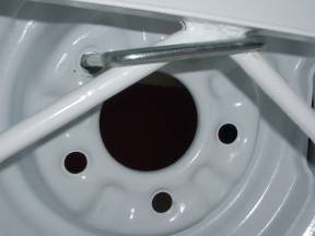
Figure 10 Hardware to mount spare
This is pretty simple, but don’t loose the hardware as it is not attached to the trailer.
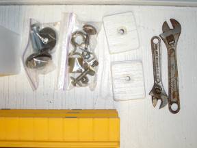
Figure 11 Hardware and tools in Ammo Box
Ammo box is in the front for the hardware and pads that holds the root of the wing on the trailer and the bolt with rubber washers for the tail tie down.
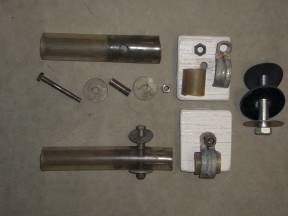
Figure 12 Root Hardware and protection
(The big plastic tubing for the drag spar pin is on the trailer pin to protect it from rust, not in the ammo bag.)
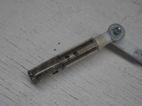
Figure 13 Plastic Protector for Rear Drag Spar on Fuselage Holder when glider off trailer
(see ammo box above)
Rear Drag Spar Pin ties to trailer with plastic sleeves on bolt to protect bolt hole and pin to protect it from the trailer. The size of the bolt hole is very critical. It has already been reamed to the larger size and can’t be reamed again. Protect this hole dimension!
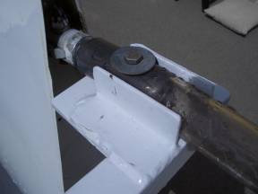
Figure 14 Rear Drag Spar Pin Bolted to Trailer
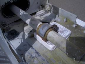
Figure 15 Main Spar bolted down with clamp and plastic over aileron tube.
The aileron push tube will slop around, even if the aileron lock is on. This clamp and plastic tubing goes under the nut which holds the main spar to the trailer.
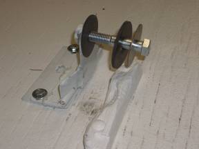
Figure 16 Bolt and Rubber Washers to hold down tail
Strap with buckle to tie wheel wing to trailer. (not pictured) store in side box or Ammo Box
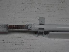
Figure 17 Fuselage holder in clip tied to trailer floor for when driving without glider
This thing flops around when driving the trailer without the glider. This little clip will secure it down to the bed of the trailer during empty transport.
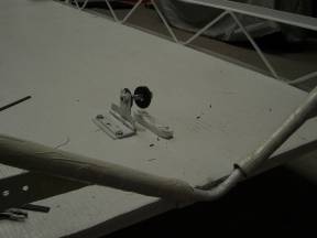
Figure 18 Pipe insulation with white duct tape
This rug is stored under the Saw Horses upside down so as not to collect dirt. (not pictured) They lay in the leading edge support bolted to the bed of the trailer
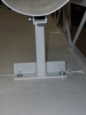
Figure 19 Leading edge support.
Remember to put rug in first! (not pictured)
Without shims, the spar will rest on the bolt heads. To evenly distribute the load Shims the height of the bolt heads are added.
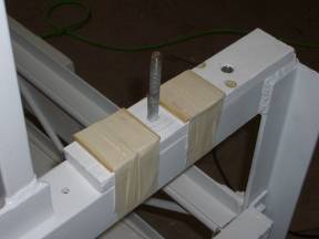
Figure 20 Shims just taped in place at the moment.
You can see the marks left by the bolt heads on the Spar
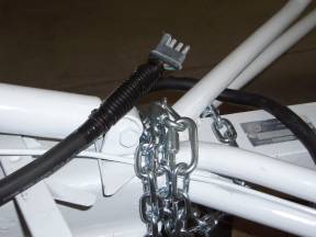
Figure 21 Safety Chain and flat four plug
Note the wire size increases to carry the electrons 35 feet. The weight of the wire could disconnect the plug from the retrieval vehicle, so be careful.
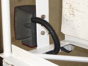
Figure 22 Light Assembly wired and protected
Protection could be better, so check that wear has not occurred where the wires run through the trailer.