|
|
|
Free Web site hosting - Freeservers.com
• Web Hosting - GlobalServers.com
1-70
Rev. 4-72
SECTION ONE – FLIGHT
PROCEDURES
Flight
Controls
Pre-Flight
Inspection
Weight
and Balance
Aero
Towing
Auto
or Winch Towing
Take-off
– Spins – Aerobatics – Dive Brakes – Slipping
Landing
Procedure – Normal and Emergency
Cold
Weather Operation
Flight
Envelope
Flight
Envelope Graph (Fig III)
Performance
curves (Fig IV)
Final
Assembly Hardware List
General
Maintenance Instructions
Fabric
covering, Finish
Lubrication
Chart – Fig. I
Lubrication
Chart – Fig. II
Lubrication
Chart – Fig. III
Rigging
Wheel
and Brake
Annual
or 100 Hour Inspection
Annual
or 100 Hour Inspection Record
Sailplane
Tie Down
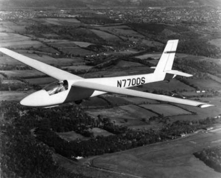
GENERAL DESCRIPTION
MODEL SGS 1-34
The SGS 1-34 is a single place, high performance, all-metal
sailplane of monocoque construction, built by Schweizer Aircraft Corp., Elmira,
N.Y.
It was designed and built to meet the need and
demand for a US Standard Class Sailplane. Its many safety features plus the
excellent flying and handling characteristics serve to make it an ideal
sailplane for the average soaring pilot; as well as one with competition in
mind.
Pilot fatigue, after long duration flights, has been
virtually eliminated because of the semi-reclining adjustable seat, adjustable
rudder pedals and adjustable headrest.
The rate of roll and controllability, while
thermalling, is very good. The visibility out of the cockpit in all directions
is excellent. The cockpit is roomy, with all the controls and instruments
within easy reach. These features add up to more pilot comfort and better
proficiency.
MODEL SGS 1-34R
The SGS 1-34R flight and handling characteristics,
form lift-off to touch-down, are identical with those of the 1-34.
The 1-34R incorporates a manually operated retractable
main gear with doors. The retractable gear offers three advantages over the
conventional gear. One, obviously that of resulting in a more aerodynamically
clean aircraft. Second, the weight of the retraction mechanism is beneficial
from a penetration standpoint. Furthermore, additional ground clearance is
provided by the extended gear for those operation from uneven fields. The
overall dimensions remain the same except for the ground height, which is
slightly increased on the 1-34R. In this connection, the gear for the 1-34 has
one inch up and down ground adjustment through the use of alternate axle holes
in the gear plates and torque arm.
Overall Dimensions
Length………………..25 ft. 5 in.
Span (15 meters)…..….49 ft 2
in.
Height……….…………7 ft. 6 in.
Wing Area………….…151 sq. ft.
Other Characteristics
1-34 1-34R
Aspect Ratio………..16……...16
Empty Weight….570 lbs. 595 lbs.
Useful Load……270 lbs. 245 lbs.
Max Gross Weight…840
lbs 840 lbs.
PERFORMANCE DATA
|
|
1-34 @ 800# GW |
1-34 @ 840# GW |
1-34R @ 800# GW |
1-34R @ 840# GW |
|
Calculated
L/D |
33 at 55 mph |
33 at 55 mph |
34 at 55.5 mph |
34 at 55.5 mph |
|
Min.
Sink |
2.4 fps @ 49 mph |
2.4 fps @ 49 mph |
2.2 fps @ 46 mph |
2.2 fps @ 46 mph |
|
Placard
(red line) Speed dive brakes closed |
135 mph |
132 mph |
135 mph |
132 mph |
|
Placard (red line) Speed
dive brakes open |
142 mph |
132 mph |
142 mph |
132 mph |
|
Stall
Speed |
36 - 38 mph |
36 - 38 mph |
36 - 38 mph |
36 - 38 mph |
Opening
the Canopy:
Access to the cockpit is gained normally from the
left hand side of the ship. The small window panel in the lower section of the
canopy is pushed slightly inward, then aft. Reach across the cockpit to the
ring on the latch handle, rotate the latch by pulling the handle ring inboard
and aft. The canopy is unlatched when the handle is at right angles to the
longeron. To latch the canopy after tie-down, reverse the above procedure.
FLIGHT
CONTROLS:
Control
Stick:
The
single bent control stick is conventional for aileron and elevator control.
Rudder
Pedals:
Rudder
pedals are conventional with a five position adjustment. Ease of adjustment is
provided for by a levered lock-pin arrangement and a spring assisted pedal
retraction.
Rudder
Pedal Adjustment Lever:
Located
between the bottom of the rudder pedals. To adjust depress lever with either
heel and relax pressure on rudder pedals. The spring will retract the pedals to
the full aft position. Push pedals forward to desired position and allow lever
to lock in place by removing heel.
Trim
Control (longitudinal):
The
cockpit control is a lever with a knurled lock-knob located on the right hand
side of the cockpit. The lock-knob must be turned counter-clockwise to unlock
and clockwise to lock.
On
the fist few aircraft, the cockpit control is a T-handle located under the
lower left side of the instrument panel. To unlock, turn T-handle
counterclock-wise. Pull to the desired trim position and lock by turning the
handle firmly clockwise.
The
trim systems of the bungee type which applies tension to the elevator cable to
reduce the control stick back-pressure required while flying at slower
airspeeds. Forward position for nose-down, trim and aft positions for
increasing amounts of nose-up trim, for either type of control.
Tow
Release Control:
The
release control is a knob located below center of the instrument panel. Pull
the knob fully aft to actuate the tow hook release.
Dive
Brake Control:
The
dive brakes are actuated by a lever located at the forward left hand side of
the cockpit. Lever is pulled slightly inboard to unlock and aft to the desired
degree of dive brake application. To close and lock dive brakes, push the lever
forward until it snaps into the locked position. Forces required to open and close
the dive brakes are light at low speeds, but will require more force to close
as speed is increased.
Main
Wheel Brake:
The
main wheel brake is hydraulically actuated disc type and is applied by unlocking
the dive brake lever and pulling to the full aft position. The wheel brake is
actuated during the final few inches of the dive brake control lever travel.
Extra pull force is needed to achieve wheel-braking action.
Instrumentation:
An
airspeed indicator, sensitive altimeter and magnetic compass are required.
Additional instruments, up to a full panel, are optional at the owner’s
discretion.
Static
Line Drain:
Provision
for draining of any accumulation of water from the airspeed static line is made
by a spring-loaded valve located at the lower left hand side of center console.
To open the drain valve, push forward on the handle pins and turn
counter-clockwise approximately ¼ turn. To close valve, turn handle pins. ¼
turn clockwise and release.
Factory
flight tests have shown that with this valve open in flight , airspeed readings
are reduced slightly. Flight with this valve inadvertently in the open position
is therefore not particularly hazardous, and, in an emergency, may be used as
an alternate source of static pressure.
Canopy
Latch:
Located
on right side center bottom canopy frame. Push down and forward to secure
canopy. Reverse to unlatch - the handle is at right angle to the longeron in
the unlatched position.
Cockpit
Ventilation:
Located
at top left side or right side of console. Adjust valve as desired.
Clear-vision
Window Panel:
Located
at left or right bottom side of canopy aft of center. To open, pull small knob
inward and slide panel aft to ventilate and remove condensation form internal
canopy surfaces.
Headrest
Adjustment Lever
Located
at center of aft hatch forward bulkhead. To adjust, pull spring-loaded lever
outboard and set headrest to desired position. Release lever to lock in place.
Six positions are provided to complement the various seat-back positions.
Seat-back
Adjustment Levers:
Located
at top outboard sides of seat back. Depress both spring-loaded levers inboard
and set seat-back to desired position in the adjustment racks. Release levers
to lock into position.
Retractable
Gear Control, 1-34R:
The
gear retraction / extension control has slide-tube and cable arrangement with a
knob handle, together with a squeeze-type finger lever latch, on the right side
of the cockpit. For “Gear Down”, the control knob is in the full forward
position; for “Gear Up”, the control is pulled to its full aft position. At
both “Gear Up” and “Gear Down” positions, the control is locked by a pin (on
the underside of the latch lever) engaging a hole in the inner slide tube. A
“Gear Down” safety pin is provided (attached to a bead chain) for insertion
through the slide tubes for additional protection against inadvertent gear
retraction during ground-handling or tie down periods.
PREFLIGHT INSPECTION
CHECK ALL POINTS AS LISTED
Fuselage
and Cockpit:
1. Flight controls for free and
normal movement.
2. Rudder pedal adjustment.
3. Seat and headrest
adjustments.
4. Release hook and linkage.
5. Instruments, lines,
pitot-static openings, static line drain.
6. Canopy - hinges and latch,
head clearance.
7. Safety belt and shoulder
harness.
8. Wing pins - main spar, and
aft carry - thru
9. Aileron control attachment,
fuselage to wing.
10. Tire condition and inflation (31 psi).
11. Wheel brake operation.
12. Nose Skid attachment and condition.
13. General condition exterior surfaces.
14. Retractable gear safety pin removed - 1-34 only.
Wing
1. Aileron hinge and pushrod
connection.
2. Dive brake and mechanism.
3. General surface condition.
Empennage:
1. Stabilizer attach, forward
and aft.
2. Elevator - hinges, pushrod
attach.
3. Rudder - hinges and fabric.
4. Remove inspection plate -
rudder and elevator control connections.
5. Tail wheel.
6. General condition surfaces
and aft fuselage.
WEIGHT AND BALANCE, SGS 1-34
The weight and balance furnished with each
sailplane, should be the concern of each pilot, to familiarize himself the
various weights, and weight distribution limits shown. The “placard limits”
plate attached to the instrument panel shows only the basic weight limitations
as to maximum pilot weight to reach either (1) maximum gross weight, or forward
CG limit, whichever is less; and (2), the minimum pilot weight to maintain the aft
CG limit. However, because of variables in loading conditions, pilot - weight
limits will also vary. For instance, the maximum pilot weight (for forward CG
limit) with the seat back in the fully forward position, will sometimes
calculate to be less than the weight necessary to obtain the maximum gross
weight. See Weight and Balance Report for the aircraft. It should be understood
that the heavier pilot will, in most cases, be tall enough to require that the
seat - back be adjusted to a position other than the fully forward position. In
such case, it is quite probable that the maximum gross weight figure is
applicable, as each succeeding position (aft) of the seat back adjustment will
allow a somewhat greater pilot weight and still remain within the forward
limit. In any case, flight at, or near, the forward CG limit condition is not
as critical to controllability as is flight at the aft CG limit condition.
CAUTION: Upon entering the cockpit,
the nose section should e pushed downward so that the nose skid rests on the
ground. Should the pilot’s own weight fail to keep the nose skid in contact
with the ground, the CG condition must be rechecked, to assure that the aft CG
limit is not exceeded, before flight is attempted. This indication of the CG
applies to the fixed gear model only.
WEIGHT AND BALANCE, 1-34R
The Datum, MAC and CG limits are identical with
those for the SGS 1-34.
The 1-34R maximum Gross Weight is 840 lbs. This
gross weight was also approved for the model SGS 1-34 and was mad retroactive
to include ships No. 1 and up.
The main wheel on the 1-34R, as stated previously,
extends farther below the fuselage that on the 1-34. The axle position is also
moved forward approximately eleven inches. This has no effect on the weight and
balance outcome - only the figures use in some computations.
AERO TOWING
Use normal aero tow procedures. The actual take-off
should not be attempted until an IAS of 40 mph is reached. Due to the low angle
of attack, a slower attempt of take-off will result in a series of tail bumps
which will be severe if the terrain or runway is not smooth. The recommended
aero tow speed is 55 - 60 mph. Towing slower than an IAS of 50 mph is not
recommended.
AUTO OR WINCH TOWING
Both the SGS 1-34 and SGS 1-34R have been flight -
tested and approved for auto-winch towing at maximum gross weight. However,
with the release hook so far forward of the CG, this manner of launch is
something less than ideal. Therefore, not recommended for any pilot without
proper instruction or equivalent experience.
Normal auto or winch tow procedures are used,
however, as the tow hook is so far forward, the sailplane has a porpoising
tendency when too much up elevator is used for the climb. Should this occur,
reduce back pressure on the stick until
the porpoising stops. The maximum tow speed of 66 mph must be observed.
TAKE-OFF
The take-off characteristics for the 1-34R a
different form the 1-34 because of the more forward location of the main
landing gear. For this reason, a forward pressure on the stick is required to
raise the tail off the ground to attain a level flying attitude for take-off.
SPINS
Spin entries, rotation and recoveries are all normal
throughout the CG range. The following characteristics occur as the CG is moved
rearward.
1.Entries will be more difficult.
2.Rotation will be slower and flatter.
3.Control movements for recoveries more pronounced.
4.Slower recovery, but will not exceed 3/8 - ½ turn
at aft CG limit.
5.Slower indicated airspeed upon recovery.
6.Less loss of altitude per rotation.
AEROBATICS
The 1-34 is fully aerobatic, but due to the danger
of easily exceeding the maximum placard speed from a poorly executed maneuver,
it is highly recommended that pilots without aerobatic experience either not
attempt aerobatics, or get instruction prior to engaging in such flight.
DIVE BRAKES
Dive brakes can be used for rapid loss of altitude
at any time, including the normal landing procedure as described below.
The 1-34’s dive brakes are extremely effective and
will limit the aircraft’s speed to approximately 142 mph in a vertical-attitude
dive at full gross weight. This is an a
hold over error from the first version of this manual. At the new gross weight
the Vne is 132. To maintain a given IAS the nose must be lowered as the
dive brakes are pulled open. The reverse is true when closing them.
SLIPPING THE AIRCRAFT
Slips can be executed normally, but with the
effectiveness of the dive brakes it is unlikely that slipping should become
necessary.
LANDING PROCEDURES
A.
Normal Landing:
Pattern It is standard practice to fly a normal traffic pattern.
Allow extra airspeed as necessary depending on gust and wind conditions.
Approach The approach should be made high with use of dive brakes as
needed. They increase both sink and drag which, in turn, creates a steeper and
more controllable glide path.
Touch Down Can be made with dive brakes fully open, partially open, or fully
closed. However, the latter is not recommended except for practice or the
stretch out a lancing approach. The actual landing should be make at an IAS of
40 - 45 mph. Do not touch down less than
45 mph. Landing at a slower speed will result in a tail first landing.
On the 1-34R the main wheel is located in a
more forward position. For that reason forward pressure is used during the
landing roll and stick movement increased as airspeed decreases, until elevator
control becomes lost and the tail wheel contacts the ground.
Ground Run After touch-down, the aircraft should be literally flown to a
stop. Care should be taken to keep the wings level and the track straight. When
taxiing in a cross wind, keep the upwind wing low for best possible control.
Wheel Brake May be used at any time, and to any extent, for as quick a stop
as desired after touch down. The aircraft can be landed with the wheel brake
fully on. This will not cause the sailplane to nose over, although an
abrupt rotation will occur until the nose skid makes contact with the ground.
B. Landing, Dive-Brakes Inoperative
- Emergency Procedure:
In the event that the dive brakes should become
inoperative, in which case the wheel brake would probably be also inoperative,
the correct landing procedure is:
1.
Enter pattern
at lower than normal altitude.
2.
Fly pattern at
a slow but safe speed (45 -50 mph).
3.
Slip as
necessary at an indicated 45 - 50 mph until sailplane is ½ wing span from the
ground.
4.
Raise low wing as
altitude decreases, but hold in full opposite rudder.
5.
At 2 to 3 feet
above ground, wings should be level and opposite rudder eased off to neutral
position (straight and level flight).
6.
From 2 to 3
feet force the sailplane gently but firmly to a flying touch-down.
7.
Upon
touch-down, Immediately but slowly, push the stick full forward so that the
skid will contact the ground and assist in braking to a stop.
It is rather difficult to land a high performance
sailplane using the above procedure. Therefore, some practice landings of this
type would be very beneficial for a future emergency. However, since an
inoperative dive brake is considered to be a remote possibility, a pilot should
not attempt to practice this emergency procedure until he has become thoroughly
familiar with the normal flight and handling characteristics of the sailplane.
COLD WEATHER OPERATION OF
THE 1-34
Since the 1-34
may be used in wave and winter flying, it is recommended that a
low-temperature lubricant be used on all pivot points, bearing surfaces, and
other moving parts. To do this, the pins and bolts should be removed and
cleaned of any old grease or ail with a solvent. Apply low-temperature grease,
such as Esso “Beacon #325”, or equivalent, which meets low-temperature
requirements of Spec. MIL-G-3278 (See QPL-3278)
DIVE
BRAKE FREEZING:
Two types of freezing are possible with the dive
brake system. The first is the actual freezing down of the dive brake doors and
the second is the high friction of the dive brake control system due to the low
temperature effect on lubricants.
Snow or ice on the top surface of the wing will
usually be melted by the sun which results in a water film in the dive brake
door recesses. In flight, as the air cools with altitude, this water freezes
the doors into the recesses so that they may not be opened. It is recommended
that the doors and recesses be checked and dried off if flying in freezing
weather is expected or intended.
The dive brake system should be cleaned and
re-lubricated with low-temperature grease as previously stated.
ICE,
FROST OR SNOW ON SAILPLANE:
Ice, frost or snow on a sailplane can be dangerous
in that is greatly increases stalling speed. All ice, frost and snow should be
removed from the sailplane prior to flight. This can most easily be done by
cleaning off the excess and then letting the sun melt the rest. If heated
hangars or blowers are available, they can be used. Be sure surfaces are dry
before attempting flight. Do not scrape ice, snow or frost from surfaces as
this is likely to scratch the finish, or possibly gouge the skin.
CANOPY
PROVISIONS:
Be sure that the bolts and nuts holding the plexiglass
to the canopy frame are only snug so that plastic can move as it expands or
contracts. It is recommended that clear-view panels be installed inside the
canopy to provide a dead air space. Use of the ventilating window may not be
practical at extremely low temperatures.
WHEEL
FREEZING:
When operating through slush or mud, it is possible
that the wheel well may become filled during one or several take-offs and
landings. Then during flight, if temperature droops sufficiently, slush may
freeze and lock the wheel. There is no remedy for this except to avoid the
slush and mud. The consequence for landing with a wheel locked is not severe -
at most, a blown tire could result.
On the SGS 1-34R, the above conditions hold true,
but with the additional possibility of the retraction mechanisms and doors
becoming frozen in the “gear up” position. While this is undesirable, a nearly
normal landing can be made on the nose skid without necessarily damaging the
sailplane. Allowances should be made to compensate for the absence of the
wheel-brake in such an instance.
1-34 and 134R FLIGHT
ENVELOPE
The graph on the following page (Fig. III) shows the
basic Flight Envelope. The aircraft should be operated within the envelope
limits at all times. Note the different maximum speeds allowable with or
without use of the dive brakes. From points A to C and A to J abrupt maneuvers
will not exceed the load factor indicated by this line. Above C (83mph) the
maneuver must be limited to avoid excessive load factors. The gust lines are
based on the standard 24 ft/sec. Gust. In case of extreme turbulence, such as
found in wave conditions and clouds, gusts can be much higher and the aircraft
should be operated as slowly as practicable, considering the fact that under
turbulent conditions a safe margin above stalling speed should be maintained.
Keep in mind that while the load factors in the
Flight Envelope carry a 50% margin of safety, these margins should not be
used intentionally - they are for inadvertent conditions only. This is also
generally true for over-speeding. A 20% increase in speed above the placard
limit will use up the margin of safety. A wise pilot will never use greater
speed, or pull more G’s that the condition requires.
A word of caution on aerobatics. Sailplane
aerobatics is a specialized field and requires instruction and experience to
accomplish safely. As previously stated in this manual, it is all too easy to
exceed flight limits in a improperly executed maneuver, and for that reason
aerobatic flight is not recommended.
PERFORMANCE CURVES
To aid the serious pilot in becoming familiar with
the various L/D vs. Airspeed relationships, a graph of the calculated
performance curves, at maximum gross weight, is provided for his information.
See Figure IV.
Fig. III
n7595.freeservers.com/flightenvelope.jpg
Fig. IV
n7595.freeservers.com/performancecurves.jpg
Design Data
n7595.freeservers.com/one34manualperformanceweb.jpg
Annual Check List
and Lube Chart